Clear up the confusion between grounding and bonding once and for all. Essential knowledge for Article 250 questions on the trade exam.
Grounding and bonding are among the most confused concepts in electrical work — and among the most heavily tested topics on the CSLB C-10 exam. Let's break them down clearly once and for all.
The Fundamental Difference
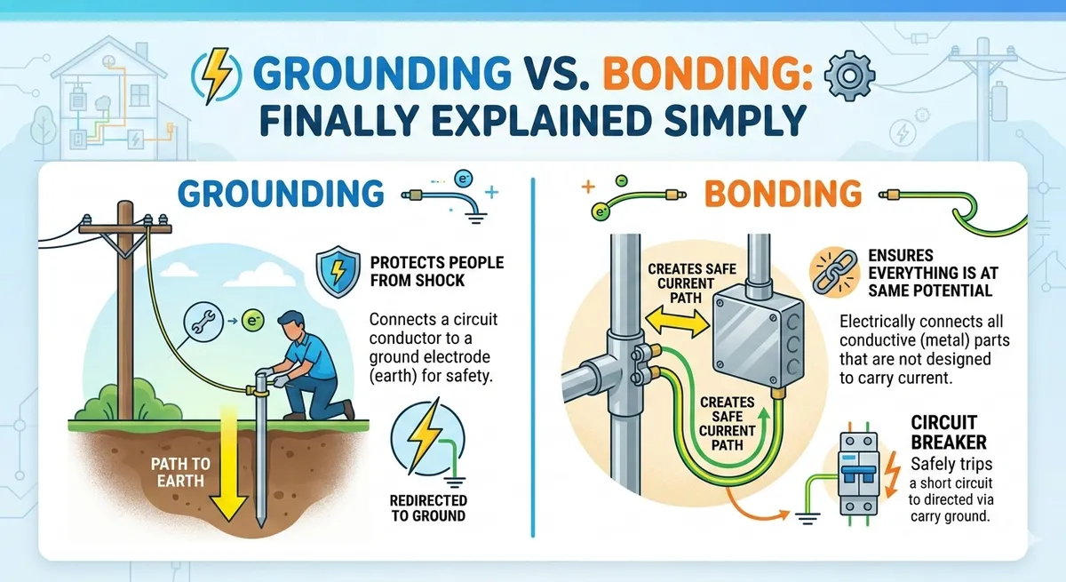
The simplest way to remember: Grounding connects the electrical system to the earth.Bonding connects all conductive parts together. They serve different safety purposes:
- Grounding (earthing): Establishes a reference point for the electrical system and provides a path for lightning and surge dissipation. The grounding electrode conductor connects the system neutral to the grounding electrode (ground rod, water pipe, concrete-encased electrode, etc.).
- Bonding: Ensures all metal parts in an electrical installation are at the same electrical potential. This prevents shock hazards and ensures fault current can flow freely to operate overcurrent devices. Bonding creates a low-impedance path for fault current.
Key Concept for the Exam
Grounding alone does NOT clear faults — bonding does. The purpose of bonding is to create a low-impedance fault current path so that the overcurrent protective device (breaker or fuse) will operate quickly. Without proper bonding, a ground fault could energize metal parts indefinitely without tripping the breaker.
Article 250: The Grounding Bible
Article 250 of the NEC is the longest and most complex article. For the C-10 exam, focus on these sections:
Grounding Electrode System (250.50)
All of the following electrodes that are present at the building must be bonded together to form the grounding electrode system:
- Metal underground water pipe (first 10 feet entering the building)
- Metal frame of the building (if effectively grounded)
- Concrete-encased electrode (Ufer ground): 20 feet of ½" rebar or #4 bare copper encased in 2" of concrete at the bottom of a footing
- Ground ring: #2 AWG bare copper, 2½ feet deep, encircling the building
- Rod and pipe electrodes: 8-foot ground rods driven into the earth
Grounding Electrode Conductor (GEC) Sizing — Table 250.66
The GEC connects the grounded service conductor (neutral) to the grounding electrode system. Size it based on the largest ungrounded service-entrance conductor:
- Service conductor: #2 AWG copper → GEC: #8 AWG copper
- Service conductor: 1/0 AWG copper → GEC: #6 AWG copper
- Service conductor: 3/0 AWG copper → GEC: #4 AWG copper
- Service conductor: Over 750 kcmil copper → GEC: 3/0 AWG copper
Equipment Grounding Conductor (EGC) Sizing — Table 250.122
The EGC is sized based on the rating of the overcurrent device protecting the circuit:
- 15A circuit → #14 AWG copper
- 20A circuit → #12 AWG copper
- 60A circuit → #10 AWG copper
- 100A circuit → #8 AWG copper
- 200A circuit → #6 AWG copper
Main Bonding Jumper (250.28)
The main bonding jumper connects the equipment grounding conductor, the grounded conductor (neutral), and the grounding electrode conductor at the service equipment. This is the critical connection that ensures fault current can return to the source. Key points:
- Must be installed at the service disconnecting means
- Can be a wire, bus, screw, or similar conductor
- Sized per Table 250.66 (same as GEC) or 12.5% of the service conductor for larger sizes
- The neutral-to-ground bond must occur at only one point — the main service panel. Sub-panels must keep neutral and ground separate (no bonding jumper).
Common Exam Question
"Where is the only location where the neutral and equipment ground should be bonded together?" Answer: At the service disconnecting means (main panel). In sub-panels, the neutral bus and ground bus must be isolated from each other. This is one of the most frequently tested grounding/bonding questions on the C-10 exam.
Supplementary vs. Required Ground Rods
If a single ground rod does not achieve 25 ohms or less of resistance to ground, a supplementary ground rod must be installed at least 6 feet away from the first rod. When two ground rods are installed, the 25-ohm requirement is considered met (250.53(A)(2)).
For the exam, remember: one rod = must test for 25 ohms or install a second rod. Two rods = no testing required. The rods must be at least 8 feet long and spaced at least 6 feet apart.
Recommended Articles
Mastering NEC Load Calculations for the C-10 Exam
Step-by-step guide to the most complex math problems you'll face on the CSLB C-10: dwelling unit standard and optional calculations.
How to Use NEC Tables Like a Pro for the Trade Test
Stop guessing on wire sizing. Learn how to apply temperature correction and adjustment factors correctly under closed-book conditions.
C-10 Voltage Drop Calculations: The Easy Way
Memorize these core formulas and you can solve any voltage drop question the CSLB exam throws at you.