Stop guessing on wire sizing. Learn how to apply temperature correction and adjustment factors correctly under closed-book conditions.
Conductor sizing questions appear frequently on the C-10 exam and require you to apply multiple NEC rules simultaneously: ampacity tables, temperature correction, adjustment factors, and terminal temperature limitations. Here's how to handle them systematically.
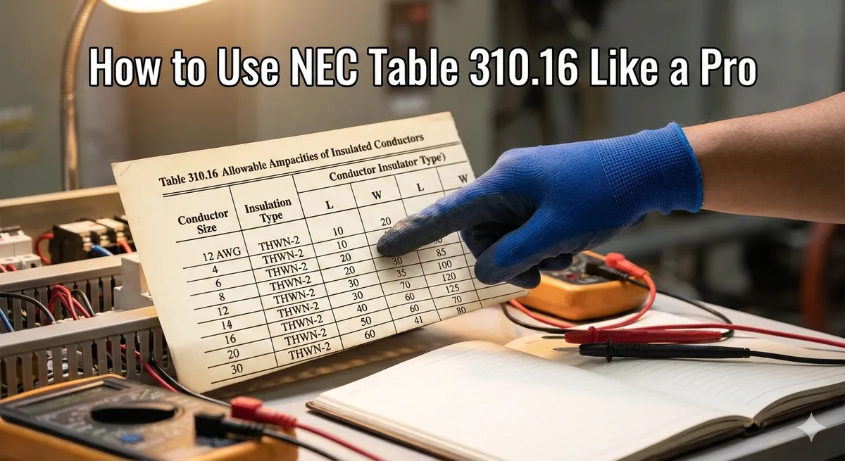
The Core Table: 310.16
Table 310.16 is the most referenced table in the NEC. It shows allowable ampacities for insulated conductors rated up to 2000 volts. The table has three temperature columns:
- 60°C column (TW, UF): Used for #14 to #1 AWG conductors on 15A-100A circuits, and when the equipment terminal is rated 60°C.
- 75°C column (THW, THWN, XHHW): Most commonly used for general wiring. Required when equipment terminals are rated 75°C (standard for most modern equipment).
- 90°C column (THHN, THWN-2, XHHW-2): Used as the starting point for applying correction and adjustment factors, but the final ampacity may be limited by the terminal rating.
The 90°C Trick
The 90°C column has the highest ampacity values. When you need to apply temperature correction or adjustment factors, start with the 90°C ampacity value (this gives you more room). After applying all factors, the final adjusted ampacity must not exceed the value from the column that matches the terminal temperature rating (usually 75°C). This approach is often the key to solving tricky conductor sizing problems on the exam.
Temperature Correction Factors
When the ambient temperature exceeds 30°C (86°F), you must reduce the conductor's ampacity using correction factors. The factors are found at the bottom of Table 310.16:
- 31-35°C: Multiply ampacity by 0.96 (90°C column) or 0.94 (75°C column)
- 36-40°C: Multiply ampacity by 0.91 (90°C column) or 0.88 (75°C column)
- 41-45°C: Multiply ampacity by 0.87 (90°C column) or 0.82 (75°C column)
- 46-50°C: Multiply ampacity by 0.82 (90°C column) or 0.75 (75°C column)
Formula: Adjusted Ampacity = Table Ampacity × Temperature Correction Factor
Adjustment Factors for Bundling (More Than 3 Conductors)
When more than 3 current-carrying conductors are installed in the same conduit or cable, you must apply adjustment factors from Table 310.15(C)(1):
- 4-6 conductors: 80% of table ampacity
- 7-9 conductors: 70% of table ampacity
- 10-20 conductors: 50% of table ampacity
- 21-30 conductors: 45% of table ampacity
- 31-40 conductors: 40% of table ampacity
Note: Neutral conductors that carry only unbalanced current are not counted as current-carrying conductors. Equipment grounding conductors are never counted. However, if the neutral carries harmonic currents (common with nonlinear loads), it must be counted.
Applying Multiple Factors Together
When both temperature correction and bundling adjustment apply simultaneously, multiply them together:
Final Ampacity = Table Ampacity × Temp Correction Factor × Bundling Adjustment Factor
Example: A #10 THHN conductor (90°C column = 40A) in a conduit with 5 other current-carrying conductors, in an ambient temperature of 40°C:
- Start with 90°C ampacity: 40A
- Temperature correction (40°C, 90°C column): × 0.91 = 36.4A
- Bundling adjustment (6 conductors): × 0.80 = 29.12A
- Check against 75°C terminal limit: 35A (75°C column for #10)
- Final ampacity: 29.12A (since it's below the 75°C terminal limit)
Terminal Temperature Limitations
This is where many candidates make mistakes. The NEC limits conductor ampacity based on the terminal temperature rating of the connected equipment:
- Circuits rated 100A or less: Use the 60°C column unless all terminals are rated 75°C
- Circuits rated over 100A: May use the 75°C column
- Exception for derating: When applying temperature correction or adjustment factors, you may start with the 90°C ampacity, but the final value cannot exceed the 75°C (or 60°C) column value
Exam Strategy
When you encounter a conductor sizing question on the C-10 exam, follow this systematic approach: (1) Identify the required ampacity, (2) Check for temperature or bundling conditions, (3) If derating is needed, start from the 90°C column, (4) Apply all correction/adjustment factors, (5) Verify the result doesn't exceed the terminal temperature column. Select the conductor that meets all requirements.
Recommended Articles
Mastering NEC Load Calculations for the C-10 Exam
Step-by-step guide to the most complex math problems you'll face on the CSLB C-10: dwelling unit standard and optional calculations.
Grounding vs. Bonding: Finally Explained Simply
Clear up the confusion between grounding and bonding once and for all. Essential knowledge for Article 250 questions on the trade exam.
C-10 Voltage Drop Calculations: The Easy Way
Memorize these core formulas and you can solve any voltage drop question the CSLB exam throws at you.